Monday, 18 February 2008

Build Day 2

Wiring


Car wiring is one of most builders least favourite stages as it's a mass of complicated same coloured wires all operating different components. Becuase of this we're going to tackle it over a few evenings as we don't want to be pulling our hair out over the build just yet.
Heres the R1 engine loom


We need to wire all the lights, switches, sensor units, clocks and then meet the engine loom. This is how it looks positioned and labeled. If you're wondering what that massive copper tube is sticking out, that's the fuel return that we haven't cut and p-clipped in position yet.

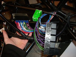
To secure the wires into place we're using rivets and p-clips but we're waiting on some larger 12mm p-clips as we just have 10mm ones at the moment.

Pedal Box


Next in is the pedal box. We have a slight concern with this as the diagonal on the bulkhead gets in the way of the accelerator pedal. Marc has assured us that it won't need to be pushed back that far but we're going to file it down to allow it to be fitted centrally. I haven't got a before shot but it was completly rounded and we've added that "v" looking section.

We're going to paint the exposed metal once were happy that everything's in place. Moving on, we marked holes where we were going to put the cylinders and bolts through the bulk head. We also marked 4 points to attach the pedals to the floor. With a 38mm hole cutter we made the brake cylinder's holes, for the bolts we used an 8mm drill bit. We then attached the m8(12.9) bolts with two washers and a non-nylocked nut. This is so we can take the box out if we need to for the clutch and accelerator cables. The bias bar (a component giving more braking force to either front or the rear brakes depending on adjustment) was fiddley to get in and isn't in the right place but will do for the mock up. This is how it now looks screwed into the brake cylinder push rods.

On the engine bay side the brake cylinders are in place with the m8 bolts, washers and nuts ready to be linked up with the front and rear brake pipes.

With some baby p clips delivered in under 24 hours from Car Builder Solutions(frankly amazing considering it came via royal mail) we were able to complete the brake pipes.
We checked everything alligned properly and that spacing was under 6 inches. Then we attached the pipes with rivets and p-clips and it now looks like this.


Scuttle panel


Like the bulk head panels we cut and shaped the big piece of aluminium to make a scuttle panel with the chassis number on. We clamped it in place, centre punched points evenly around the edge of the panel then drilled holes through the ally and chassis using a 5mm drill bit.

Sunday, 10 February 2008

Build Begins Take 2

Bulk Head Panels


The build can finally start again as the new chassis has arrived. Onto the first job, we need to rivet the bulkhead panels in place. To start with we covered the chassis in masking tape to protect it (not shown in the pictures as they're from the first attempt on the original chassis).

The two ally panels were notched and trimmed to fit exactly.

We then used a centre punch to mark rivet locaions as close to the frame as possible. Using a 5mm drill bit we drilled holes through the panel and frame in one go.

Before inserting the rivets we applied a hefty amount of clear sealant to all frame to ally points.

Then inserted 4.8mm rivets apllying quite a bit of force on the gun pumping it 2-3 times.

Here's how the two panels ended up with the protective film still in place. This time round we also riveted the diagonal piece on the drivers side to give it some extra strength for the pedals.


Brake pipes


Second job was routing the brake pipes. As ours is unlike the manual chassis, as Marc has made some more improvements :) I made a cardboard temlate then fabricated it out of some ally to to make a mounting point for the front brake 4 way "T" piece and riveted it to the chassis. Its held down by a small bolt, washers and a nyloc nut.

For the rear "T" piece we thought it would be best to get the diff and tank in position to look for the best mounting location. To get the diff in the web at the back needs to be sawn off.


We mounted the diff but behind this there isn't much space for the "T" piece. So it had to be attached on the other side in front of the tank. With the chassis masked up and hole punched we drilled straight through and applied some sealant.
We then routed the copper brake pipes to it. There are going to be two cylinders for braking; a 0.625 for the front and a 0.75 for the rear. A good idea that my Dad uses is to feed thick cable through the pipes so when bending they can't kink.
Bending the brake pipes is easy so we routed them into place by hand. To hold the pipes down we covered the area in masking tape, measured a point no more than 6 inches for the p-clips to hold the pipe down(for SVA requirements), centre punched a hole, drilled, filed, filled with sealant and then attached the p-clip with a rivet. So heres how the front and rear "T" pieces turned out.


Fuel pipes


Next up is the fuel line. Being an injected R1 engine it needs a send line (tank to engine) and a return line (engine to tank). The diff and tank need to be in to check where the pipe needs to be routed to. Not knowing the central point of the diff we just put some bolts in to hold it roughly in place. Just like the brake pipes we inserted thick cable to reduce the chance it would kink and bent it by hand. It's much harder to bend but by taking it slow and using flexible fuel hose for the tigheter bends it's achievable although it took a while. We made sure the hose type and brand were visible for SVA as the SVA man needs to know the hose is fit for purpose. Just like the brake pipes we covered the area in masking tape, measured a point every 6 inches(for SVA requirements), drilled the hole to the size of the rivet, put some sealant in and riveted the clip in place.
This picture shows the central tunnel that the propshaft sits in looking towards rear of the car. If we were to do this again we would definetly do the fuel line first as the brake pipes are easy to route around the fuel pipes and not the other way round.

This picture is from the rear looking forwards where the differential will be mounted.

Thats it for this weekend, during the week were hoping to get started on the wiring, EEP!