Sunday, 23 March 2008

Build Day 7

Now its Easter sunday the weather is shocking, freezing cold and snowing in March! Whilst revising in the morning I heard some sawing thinking that's a bit strange. Looking out the window I see my dad trimming the second interior panel outside whilst it's hailing. He used the first notched panel as a template for the other side, marked it up and then trimmed it.

Thats all for the interior panels as we're not permanently fixing the panels until other components like rear suspension and throttle and clutch cables are in.
With the interior panels pre fitted and my Dad having bought some more bolts, washers, nuts, tools and wiring clips we can finish previous stages.

Finishing the Fuel Pipe


My dad picked up a pipe bender from Screwfix so we can now bend the pipes. The prop needs to come out first to reach into the tunnel. We tried to bend the pipe with the tool, but as most of the pipe was secured half way down the tunnel it was useless as you need a lot of space to maneouver it. We were now back to stage one, simply bending the pipe by hand with cable inserted to stop it kinking. With the engine cradle in place we moved the pipe to where it could be secured without hitting the engine.

Once both were in position we could centre punch, drill (5mm), file, seal, p-clip and rivet(5mm) the pipe into place. The pipe bender did come in handy bending the pipe ends though. We then flared the ends for where the flexible pipe would start.


Finishing the Wiring


The new wiring clips we have are 20mm ID and use a m6 bolt to secure them. Using two of these clips we secured the wiring to the top of the tunnel by drilling two 6mm holes in the tunnel panel. Using 2xm6 (HT 8.8) bolts with washers and nyloc nuts we secured the clip in place.


Propshaft Refitment


After a good clean of the tunnel the prop can now go back in place. We tightened the loctited diff bolts to 69Nm. The centre bearing bolts were loctited to 76Nm.

Thats it for this weekend, time for me to watch the Grand Prix re-run as no one watches it half way through the night, except for my Dad that is. Keep checking for updates as next weekend the engine goes in!

Saturday, 22 March 2008

Build Day 6

Being the long Easter weekend we're going to try and get two days work on the car in and make some good progress. To start with is the front suspension.

Front Coilovers


We're meant to be fitting the propshaft first if were following Marc's build stage instructions. However I really couldn't resist getting the dampers, springs and rockers in place for the front inboard suspension as it's been lying in sealed boxes for months! This is our starting point.

The rockers need to be assembled first. We greased the rockers up and found everything was a very tight fit. To make this easier we put the rockers in the oven at 200 degrees centigrade (whislt my mum wasn't looking) and the cylindrical bearings in the frezzer for 10 minutes. After this they both slid together easily. 1 cylindrical bearing goes in each side of the pivoting point of the rocker, so in total there are 2 for each rocker. Then each side of the rocker needs a thrust washer, then a radial thrust bearing (a thin washer with bearings), then another thrust washer. This is repeated for the other sides. Now they can be fitted to their mounting brackets using m10 bolts cut to size, washers and a nyloc nut. To space these evenly we opened up the bracket by twisting some wood in between the bolt holes. This worked a treat and the washers could be slid into place instead of being jammed and unalligned. Heres the passenger side rocker in place.

To fit the spring to the damper we lowered the bump stop and removed the collar then the spring can be pushed over. After everything was greased up we fitted the lower coilver and bolt can be fitted. With the bracket spread apart like the rocker we fitted the m10 bolts with washers, a nyloc nut and special rod end spacers surrounding the rod end of the coilover. The coilover needs to be fitted with the adjuster facing inwards. Heres how the passenger side unit looks fitted.

This is the complete front assembly waiting for the pushrods to be fitted to the front lower wishbones.


Propshaft


As we dont have a reverse box our propshaft has a centre bearing to take the drive from the engine sproket and transfer it to the rear differential. To start the prop needs to be bolted to the diff. The diff uses 4xm10 fine bolts with serated washers and loctite.

The centre bearing needs to be fitted with 2xm6 cap head bolts (HT 12.9) with a spring washer and penny washer to spread the load. After making some markings with the prop in place we could drill the holes and then filed them out. To do the bolts up, access is gained from below through the aluminium floor. Being careful to avoid the fuel and brake lines we drilled a pilot hole first then a 12.5mm hole. We can now get the bolts in place then push the socket in to tighten the bolt up. Tool of the day here was using a telescopic magnetic pen to hold the bolt in place so the hex socket could locate the bolt into the centre bearing's thread.


Interior Panels


The next stage should be to fit the engine and connect it all up. Were not doing this as we're waiting on a last prop-to-diff bolt, we need to get a pipe bender to bend the fuel pipe into position as the bend is far to tight for us to do by hand now and our wiring is still hanging freely in the tunnel, needing to be secured. The plastic rear panel needs complete adjustment to fit. Room needs to be made for the tunnel and at the corners where the chassis meets the back. After a lot of filing and sawing here the result of the back.

Next is the interior side panels. We taped ours onto the outside then marked where it needed to be notched. We can't do it all now as we need the tub in place as the rear does not follow the chassis lines.

More to come tomorrow.

Tuesday, 11 March 2008

Build Day 5

Wiring stage 2


Before the diff and prop shaft can be fitted we need to make sure the wiring is secured so it cannot interfere with them. So to start with I had a bacon sandwich. Now onto the car starting at the front we checked both sides had the same amount space going to the headlights. As usual we masked where we wanted to drill, centre punched a hole with a hammer then applied the rivets and p-clips with sealant. This is how the front turned out.


This is the wiring in the tunnel. We left some slack to allow for the handbrake to be fitted easily.

At the front the rear gets a little more complicated. We need to avoid the diff, suspension and wishbones, brake lines and the fuel tank. So we know what room we had we fitted the tank and diff.
This is the wiring comming out of the tunnel

Here is the wiring that splits behing the diff to go the rear right and left lighs.

Finally from the split the wiring ends up at the rear of the chassis.

Differential


Having got the diff in place a few times we knew this job wasn't going to be easy. The reason being is that the diff is very heavy for its relative small size and the bolts don't allign. For starters we checked we could remove the drain plug using a 10mm hex socket and then we left it slighlty loose for when we fill it with oil. The diff mounting with the holts for bolts is made of thick steel taking a long time to file these obscured holes out. For the fitting, the diff went in from underneath with the nose pointing into the tunnel first. Once in position we held the diff roughly in place with two pieces of rope. We then fitted the shortened 2xm10 (ht8.8)top 19mm head bolts first. Then with a bit of struggling we got the bottom standard length m10's in.

We fitted the diff first without nylocs and washers so we could get it in easily and make sure it was central to the prop. Now we can take one bolt out at a time and fit the nyloc nut and the correct amount of spacers. Well that sounds easy doesn't it, as we found it definetly wasn't. Getting nylocs and washers wedged in when the other side had already been tightened was really diff-icult, excuse the punn. Three bolts went in ok but the last one was too tight for 2 washers and too loose for 1 so we had to file the diff marginally. Then we had to pull tight on the ropes to get it all to allign correctly. We used grease to hold the spacers to the diff and nut. Once in we loctite'd the threads and then torqued the bolts up evenly to 60 lb/ft and marked the bolts to chassis points with red paint to check they maintain their position. All we need now is some satin black paint to cover up the little chips from fitting and where the web was removed.

Here's another picture of the diff looking at the back of the chassis with the fuel tank fitted.

Monday, 10 March 2008

Build Day 4

Today is our second rather short build day. With looming deadlines for 2 pieces of courswork and an exam, presentations and a hangover from my mates 22nd party the night before, nothing was really going to get done. My dad started early and sorted the tank out and I gave him a hand with the fuel sender.

Fuel Tank


Using all the supplied aluminium on the battery and fuel pump brackets my Dad got some more 2 mm flat bar from B&Q. He spaced the tank so it wouldn't hit the rear brake 'T' piece. Then he began to bend the flat bar giving a few mm gap for the rubber foam as it doesn compress that much.

With 2 brackets made he drilled 4 holes into the chassis. The chassis rails were then lined with foam to stop vibrations and wear.

The tank can then be bolted down with 4 M6 bolts with a standard nut, washers and a nyloc at the end.


Fuel Sender


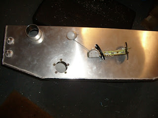
To know how much fuel is in the tank we need a sensor with a float on the end to give tank level readings. With the unit supplied from MNR we found a location for the sender, checked the movement for the float and cut off any remaining metal.

Using the 38mm hole cutter we drilled through the tank at the front(the deepest section to give the most realistic fuel gauge ratings). 5 holes then need to be drilled to accomodate the rivnuts. These are basically threaded insterts so a bolt can be used in thin metals that can't be tapped. Only problem is you need a rivnut tool to attach them which is a bit of a pain as we don't have one and they're about £20-30 from specialists. To get around this we threaded a nut to our m5 bolt that would go in the rivnut. A load spreading washer was then put on and we screwed the assembly into the rivnut and pushed it into the hole. Using 2x8mm spanners we kept the bolt head steady with one spanner and then clockwise turned the lower nut about 3 times. The effect of this is that it pulls the shaft of the rivnut towards the inside of the tank to hold itself in place almost like a rivet.
The seal is then put on with some sealant, the sender can then be fitted and the 5xm5bolts tightened with some loctite.

Sunday, 2 March 2008

Build Day 3

Scuttle panel part II


Being Mothers day my Dad went to see my Grandma so we started later than usual. As we started the scuttle panel last Sunday we wanted to get this job sorted out first. Before we permanetly riveted it down we wanted to check the battery cables could be routed to the battery and that the battery would fit. Bending some flat bar aluminium we made a battery craddle. It's held together by some 5mm rivets as although its a small bike battery it still weighs quite a bit. Where the battery would sit in the craddle we covered the flat bar in rubber stick foam strips.

With the battery live and earth in the tunnel we needed to route it to the battery. We did this by drilling 2x12.5mm holes in the tunnel panels, filed them to size and fitted 2 large wiring grommets. Then in the aluminium scuttle panel we drilled 2x10mm holes and attached 2 smaller wiring grommets. We could then feed the cables through where they would meet the battery. Minor problem with the earth as it's too short but easily sorted at a later date. Once this was done I could rivet the panel in place

Fuel pump


Today's new stage is to start with the fueling. We're starting with the pump; the Bosch unit needs to be mounted externally of the fuel tank. From having the diff in previously we knew where the pump could be mounted. Ours is going to be mounted underneath the left drive shaft on the chassis. To start with we used two pieces of ally flat bar and shaped them around the pump leaving space to put bolts through. We then used some 6mm thick rubber foam strip and laid it on the inside of the brackets we had made so the pump is held securely and can't be damaged by the bracket.

We drilled two 6mm holes through the chassis to locate the brackets. Then we passed the m6 set screws through the bracket and chassis with nuts and washers to hold it in place as tight as possible. This is how the pump looks bolted in place.

To get the fuel hose over the flared pipe I immersed them in boiling water for a few minutes then connected them up to the car with some jubilee clips.